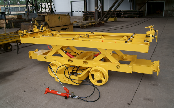
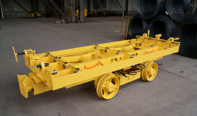
TRANSPORT PLATFORM WBA.004
Hydraulic lifting system
 The hydraulic lifting system contains of:
• 2 pieces of twosided hydraulic servomotors
YH – 10/150
• Splitting collectors MY-22 and MY-2
• Manual hydraulic pomp HPH-2/0,7,
with directional valve
• Hydraulic hoses – HHC – 10 (4 pcs.) and
HHC – 20 (2 pcs.)
YH-10 hydraulic servomotors built-up between the undercarriage and the jack aim at placing the jack’s axis in the carriage’s axis, which changes the jack’s shoulders’ angle and as a result lifts the lifting frame to the level of loading SBS-type batteries.
HPH-2/0,7 is used to compress the hydraulic oil to the working pressure. The capacity of the pomp is adjusted in such a way that ensures that the entire system is filled when operating. The built-up direct valve on the pomp VHH-4/3 determines the direction of pressing, onto the MY-22 collector (left setting), onto the MY-2 collector (right setting) and it slackens the system (central setting).
The working factor is divided into two servomotors evenly by means of MY-22 collectors (under the cylinders’ pistons) – cylinders lift the carrying frame, MY-2 (over the cylinders’ pistons) – it is possible to force the carrying frame to lower in case of its jamming when lifted.
The dividing collectors are placed in a transporting container under the undercarriage’s frame and are connected to the servomotors by means of HHC-10 pressure hoses and HHC-20 pressure hoses with hydraulic pomp. Such a solution allows alternative supply of the working factor under pressure of 700 bars from the manual pomp or outer hydraulic net.
Loading and unloading.
 Loading and unloading of the platform should t ake place, after it has been placed on a horizontal rail, after it has been protected against self-displacement and placing the carrying frame on an appropriate level, by means of appropriate lifting devices by observing the work safety regulations. The main assumption of the platform’s construction is the fact that both, loading and unloading of the battery being transported will take place by the appropriate horizontal shift thereof onto the platform on the appropriate level of loading:
• when loading – onto the platform
• when unloading – from the platform.
In order to load the transported battery onto the platform, one should follow the instuctions:
• take out the manual pomp out of the container, check its connection with the lifting system, set the direct valve lever in the left setting;
• lift the carrying frame (il. 1, pos.2) by means of servomotors powered by the manual hydraulic pomp up to the desired height (max.880 mm) and set the blockades that are to protect against emergency unstuffing of the lifting system.
• after the safety measures of bolts have been removed (il.1, pos.14), rake the bolts
(il.1, pos.14) in the outer direction and disengage the setting screws (il.1, pos.36).
After the transported battery has been loaded onto the platform, it should be protected against sideway displacement by means of bolts (il.1, pos.14) – by turning them in the inner direction and placing the bolts’ safety measures (il.1, pos.24), as well as against longitudinal displacement by means of setting screws (il.1, pos.36) by tightening them up and lowering the carrying frame of the platform to the minimum level. The trigger valve of the manual pomp (the large knob) is to be used to lower the carrying frame along with the load.
The unloading of the transported battery from the platform should be performed after the prior lifting of the platform to the unloading level, raking of the bolts (il.1, pos.14) outside (to the vertical position) and unscrewing of the setting screws (il.1, pos. 36).
It is not allowed to lift the loaded platform by means of any lifting devices.
Because of larges masses of the transported elements, the user should design a manual that specifies:
• the way of loading and unloading of the platform used to transport batteries taking into consideration its transverse stability during transport.


